LED Light Bar Assembly Adhesion Test Report 20260728018
Test Request Information:
| Requesting Dept. | Quality Dept. |
| Reason | Sample Testing |
Sample Information:
| Sample Name | LED Light Bar Assembly |
| Sample Model | ********、 ******** |
| Sample Qty | 1 PCS |
| Sample Received | 2026.07.26 |
| Test Dates | 2026.07.28 |
Test Requirements:
| Test No. | Test Item | Reference Standard | Test Requirement |
|---|---|---|---|
| 1 | Adhesion Test | Per GB/T 9286-2021, cross-cut test on the lamp cover appearance surface. | The grid area shall show no visible damage. Damage at grid intersections and scratches shall not exceed 15% of the grid area. Classification 2 or better passes (class 0, 1, 2 pass). |
Test Results: Test passed; no coating detachment.
Tested by: Test Engineer Reviewed by:
Approved by: Date: 2026.07.28
Test Samples:
| Sample No. | Sample Name | Sample Model | Sample Qty |
|---|---|---|---|
| 1 | LED Light Bar Assembly | ********、 ******** | 1 PCS |
Sample Photos Before Test:
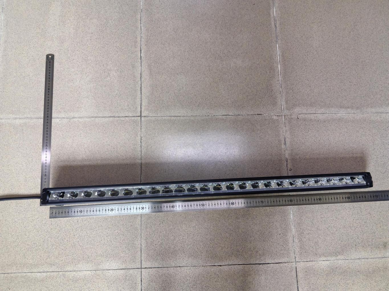
Sample 1
Test Procedure: Adhesion Test
1、 Test Equipment:
| Equipment Name | Equipment No. | Calibration Valid Until |
|---|---|---|
| 3M 681 tape | / | / |
2、 Test Conditions:
Test environment: temperature (23±2)°C, relative humidity (50±5)%.
3、 Test Basis:
Per GB/T 9286-2021, cross-cut test on the lamp cover appearance surface.
4、 Test Steps:
1、 Before the test, condition the panel for at least 16 h at (23±2)°C and (50±5)% RH.
Hold the cutting tool with the blade perpendicular to the panel surface. Apply even force at a uniform speed to
2、 make 6 cuts through the coating. All cuts shall reach the substrate, with scratches as shallow as possible. Repeat to make 6 parallel cuts at 90° to the first set,
forming a grid pattern.
The cutting spacing in each direction shall be equal and depends on coating thickness and substrate type, as follows:
as described below:
3、 Coating ≤60 μm on hard substrates (metal, plastic): 1 mm spacing;
≤60 μm on soft substrates (wood, plaster): 2 mm spacing;
61–120 μm on hard and soft substrates: 2 mm spacing;
121–250 μm on hard and soft substrates: 3 mm spacing.
Place the tape center on the grid, parallel to one set of cuts (see Fig. A.1), then
flatten the tape over the grid area. The tape shall completely cover the grid. To ensure good contact with the coating, use a
4、 rub the tape firmly with a fingertip or fingernail. Within 5 min of application, hold the free end of the tape and peel it off smoothly within 0.5–1.0 s at an angle as close to 60° as possible. Depending on coating type and cut direction,
the tape may be applied and peeled multiple times. Use new tape for each grid area. For
coatings on non-porous substrates, visually inspect the peeled tape back for potential substrate residue.
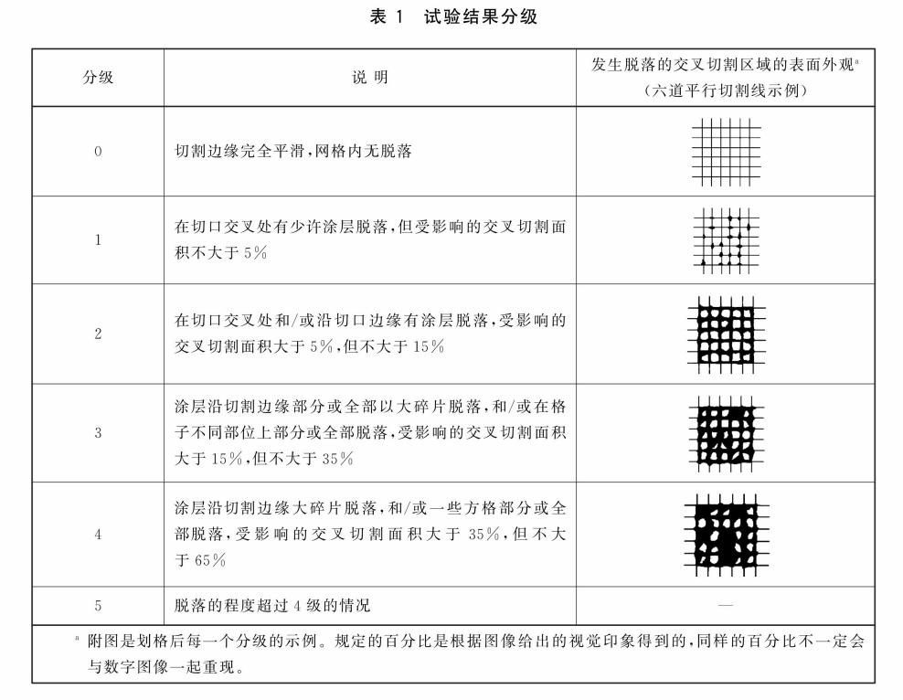
5. Evaluate test results.
5、 Test Results: see table below
| Sample No. | Test Item | Test Requirement | Test Result |
|---|---|---|---|
| 1 | Adhesion Test | 。 and 15%。 Result 2 at (0、1、2 | Test passed; no coating detachment. |
Test Photos:
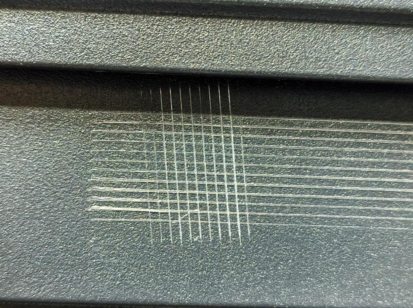
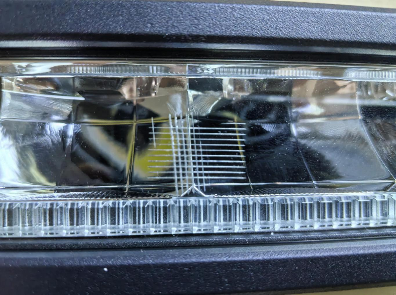
During test · During test
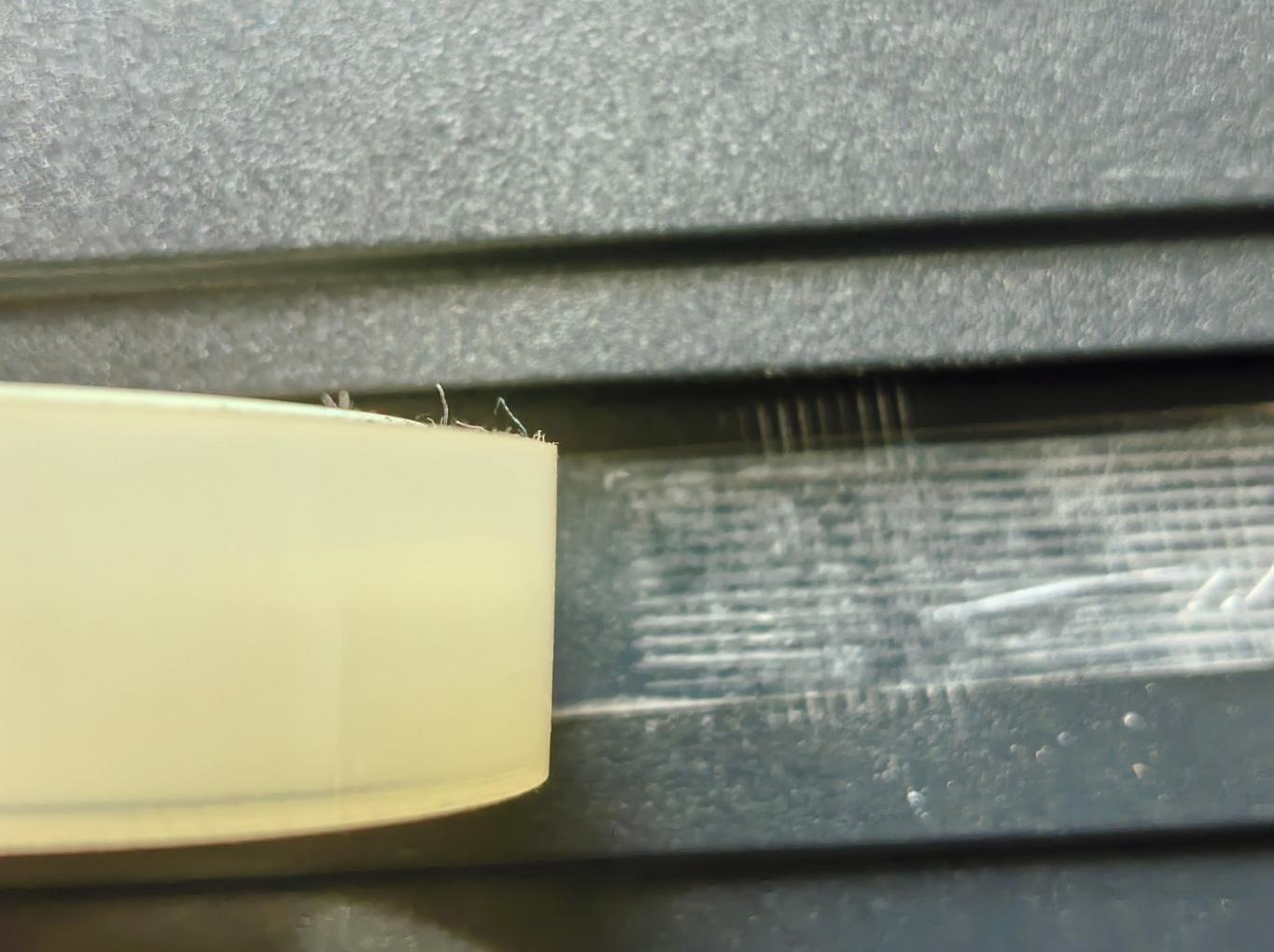
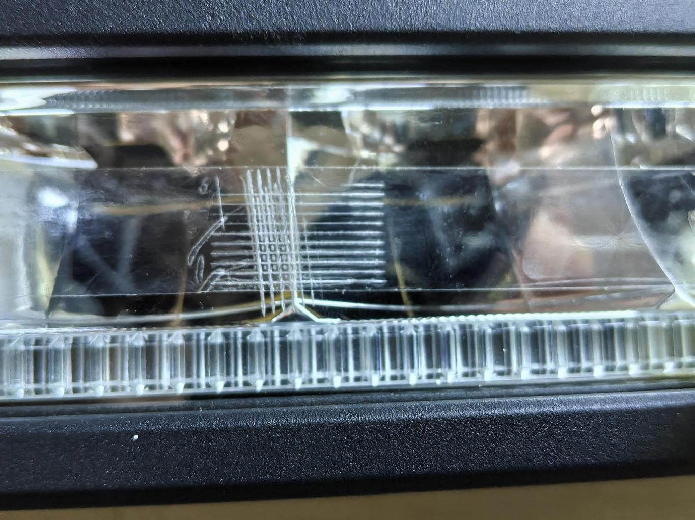
During test · During test
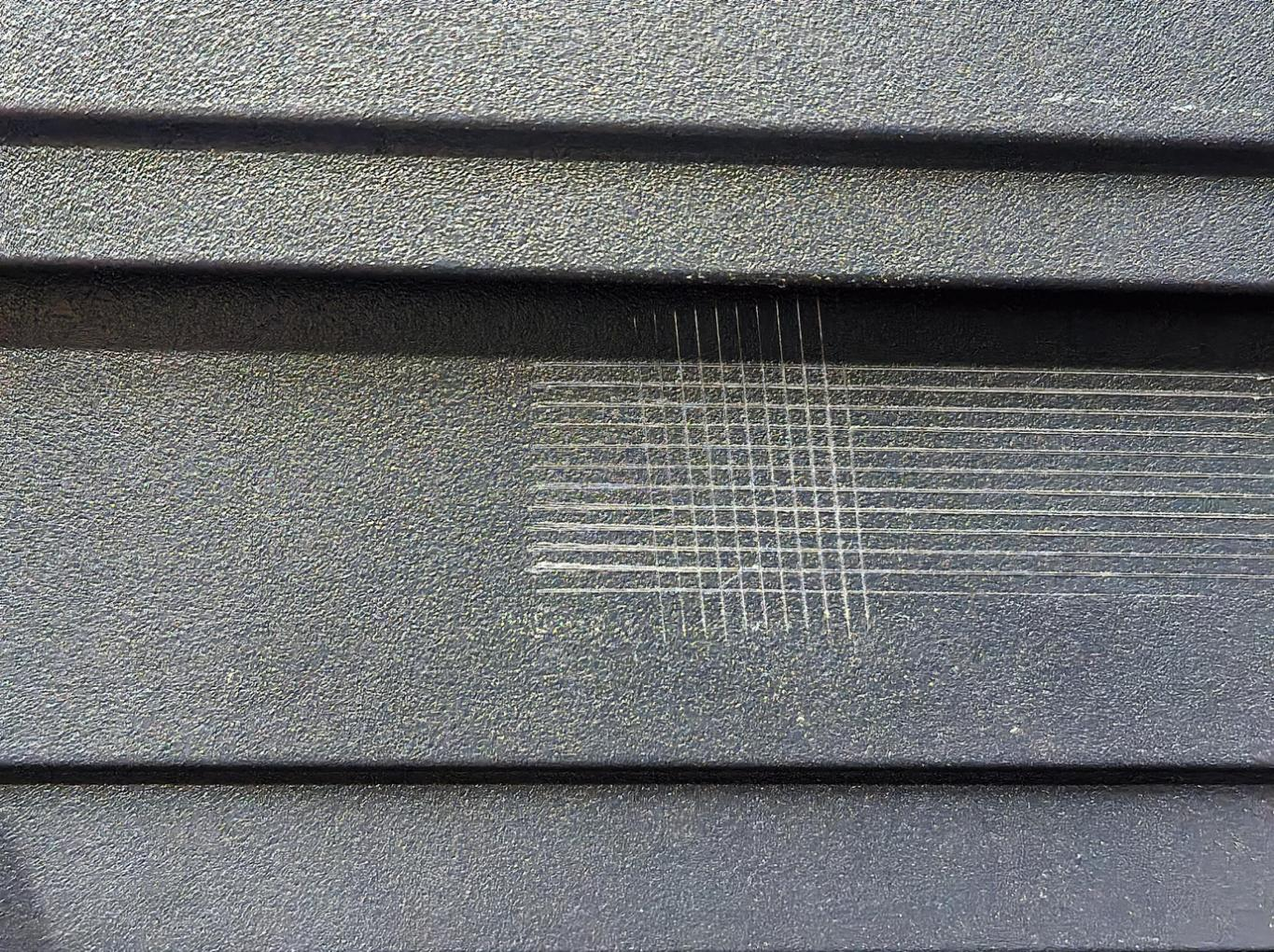
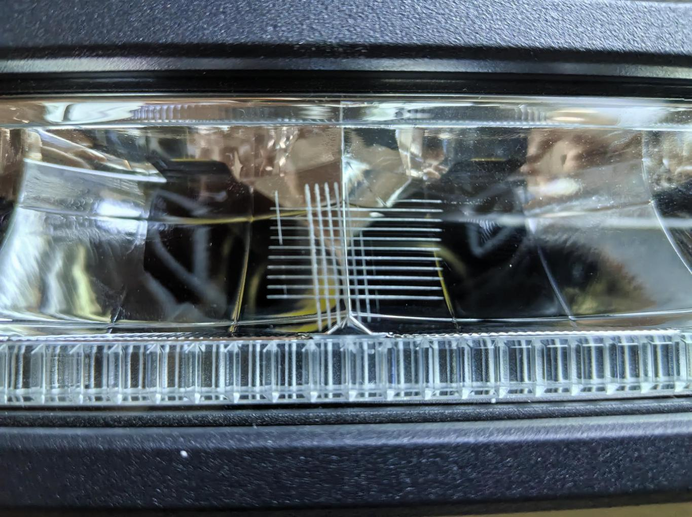
After test · After test
*** End of Report ***
Need validation data like this for your OEM/ODM project? Aurora engineering responds within one business day.
Request a QuoteExplore Our Manufacturing